How an Air Source Heat Pump Works: A Step-by-Step Diagram Guide
Published:

How an air-source heat pump works, step by step
An air-source heat pump does not burn fuel or heat a coil to make warmth. It uses electricity to move heat from outdoor air into your home, using a sealed loop of refrigerant (a fluid that circulates around the heat pump, picking up heat in one place and releasing it in another).
Heat naturally flows from warmer places to colder ones. On a cold day, your home needs the opposite: heat has to travel from the colder outdoors to the warmer indoors. The key to doing that is a relationship between pressure and temperature. When the pressure of a gas rises, its temperature rises too. When the pressure falls, its temperature falls. A heat pump uses that to make the refrigerant colder than the outdoor air at one point in the loop, and hotter than your heating system at another.
Here is the cycle in order:
- Outdoor air is drawn across a coil. A fan pulls air over the heat exchanger known as the evaporator, which takes heat from the air. Even cold air contains some heat.
- The refrigerant absorbs that heat. The refrigerant inside the evaporator is cooler than the air passing over it, so heat flows into it. The refrigerant leaves the evaporator as a gas.
- The compressor squeezes the gas. The compressor moves the refrigerant around the loop and compresses the gas. Compressing it raises its pressure and therefore its temperature, to the level needed for the heating system.
- Heat is released indoors. The hot refrigerant gas flows through a second heat exchanger, the condenser, which gives up heat to the central heating system. As the refrigerant loses heat, it condenses back into a liquid.
- The refrigerant is reset. An expansion valve lets the pressure drop, which cools the refrigerant right down. It is now cold enough to absorb heat from outdoor air again, and the cycle repeats.
If you have ever felt warm air at the back of a fridge, you have met the same principle. A fridge moves heat out of its cold interior into your kitchen. A heat pump aims the same process at a different job: collecting heat outdoors and delivering it indoors.
Reading the labelled diagram and understanding the heat-flow cycle
The diagram follows the refrigerant around the four main components. The blue inlet shows heat absorbed from outdoor air; the condenser releases heat to heating water or indoor air. Electricity drives the compressor and also powers the fan.
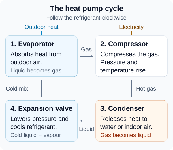
Simplified heating-mode schematic. The boxes show the sequence, not where the components sit inside or outside a home. Component roles follow the Energy Saving Trust heat pump installer toolkit.
The refrigerant loop is the line that joins all four parts and runs in one direction. Here is what to look for on any labelled diagram:
| Label | What it does |
|---|---|
| Fan | Draws outdoor air across the evaporator |
| Evaporator (heat exchanger) | Takes heat from the air into the refrigerant |
| Compressor | Moves the refrigerant and compresses the gas, raising its temperature |
| Condenser (heat exchanger) | Gives up heat to the central heating system |
| Expansion valve | Drops the refrigerant's pressure so it becomes cold again |
| Refrigerant loop | The sealed circuit connecting the parts |
When reading a diagram, trace the loop from the evaporator round to the condenser. Heat arrives at the evaporator and leaves at the condenser. The electricity is not the heat itself. It mostly powers the compressor and the fan.
Why you can get more heat out than electricity in
A resistance heater turns every unit of electricity directly into heat, so it can at best give you one unit of heat for each unit of electricity. A heat pump spends its electricity on moving heat that already exists in the outdoor air. The heat delivered indoors is therefore the heat gathered from the air plus the energy added by the compressor.
The ratio is usually expressed as the coefficient of performance (COP): heat delivered divided by electricity used. A seasonal version, SCOP, averages performance across a heating season. These figures are useful for comparing machines, but real performance varies with your home, the installation and the weather. This article does not give numbers, because they depend on those conditions.
Where the heat goes next
What happens at the condenser depends on the type of system:
- Air-to-water: the condenser passes heat to the water in a wet central heating system. That water can then feed radiators, underfloor heating and a hot water cylinder.
- Air-to-air: warm air is the heat transfer medium rather than a water-based circuit. Indoor fan units deliver the heat directly into rooms.
You may also see the terms monobloc and split. These describe how an air-to-water system is arranged, not different kinds of heat pump. In a monobloc, the evaporator and condenser sit together in one outdoor unit. In a split system, the evaporator is outside and the condenser is inside, with refrigerant piped between them rather than system water.
Once you can follow this loop, you can read almost any heat pump diagram or product description. If you want to see what a heat pump might mean for your own home, the free Heating Finder calculator lets you describe your home and compare options using visible, adjustable assumptions. It is an independent estimate, not an installer quote.


